MCP3208 with Raspberry Pi (until 05/2021)
MCP3008
Reading analog signals from external sensors with MCP3008[1] is well known and wide-spread[2],[3]. I was also working with this chip on my first experiments with photoresistors, but figured out, that 10 bit resolution would not suffice my needs.
MCP3208
So I went on for the next higher ADC model, the MCP3208[4], which provides 8 channels at 12 bit. Naturally, I was hoping for a "plug-and-play" upgrade, having just to replace the chip and start measuring in ~0.0122 V steps (5V reference).
Well, there were a couple of things in the way....
Python SPI
I took the Python code from [2] and added code for a stepper motor control (more on that in another project).
The values looked garbled, and the reason is clear: the SPI interface messages must be adapted as discussed in [2], in depth in [5].
def ReadChannel(channel):
You may want to try more parameters, e.g. spi.xfer2([ 6 | (channel&4) >> 2, (channel&3)<<6, 0], 500000,1000). Check [9] for their meaning.
adc = spi.xfer2([ 6 | (channel&4) >> 2, (channel&3)<<6, 0])
data = ((adc[1]&15) << 8) + adc[2]
return data
After fixing this, it still did not show the expected results, values were erratic, what else needs to be done? Would I have to add an amplifier, as mentioned in [5] and [6]?
Constant power source and capacitor
Equation 4.1 in [5], shows how the output value derives from input voltage and reference voltage. There is discussion about using 4095 vs. 4096, as mentioned in [2] . I use 4095, as this is the maximum output value read from the device:
value(out) = 4095 x V(sample)/V(reference)
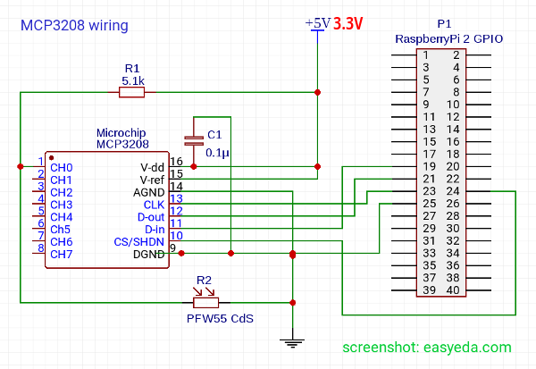
While trying to establish the measurement setup, V(sample) is kept equal to V(reference), as I am using a simple voltage divider curcuit, with large resistance ~2MOhms to Ground vs. 5.1kOhms to channel 0 of the MCP3208.
[6] "Basic SAR ADC Operation" describes how an analog voltage is transformed into a digital value by means of a capacitive array. For 500kHz, the default SPI clock speed, it takes ~3µs to sample 12 bit . So if power oscillates within this time the values will not be stable. From figure 4 we take, that we should not run at much higher clock speeds, because the higher the sample resistance is, the more time it takes to charge the capacitors. Giving it too little time for charging and reading to fast would yield bigger errors.
Attaching a power source unit at 5 V (or 3.3V, see below!) replacing RPi's GPIO 2 +5V out, yields much better results!
Monitoring RPi's GPIO 5V out with an oscilloscope revealed many jumps in voltage, mostly < 0.05 V. This would explain why driving the MCP3008 with RPi power suffices most needs.
Still, there were occasional single jumps of +- 5 counts, how about them? The countermeasure is a 0.1µF ceramic capacitor between VDD and Ground, also mentioned in [7].

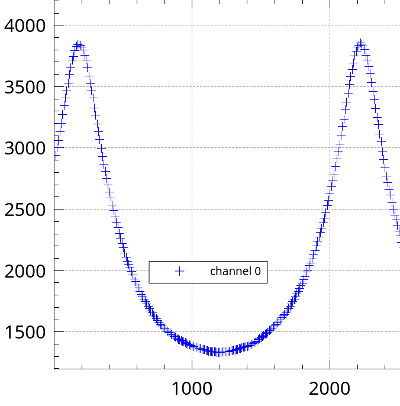
After these modifications I read reproducible values, yielding smooth curves.
I used this in my Polarimeter project on instructables[10]. The complete wiring diagram for this is available as a public project in easyeda [11].
If you are looking for higher resolution or the I2C protocol, checkout the ADS1115 page [12].
A reader from Mexico (Thanks, Pablo!) pointed out correctly, that in this setting D-out (Pin 12) connected to SPI-0 MISO (Pin 21, BCM 9) is driven with 5V, while GPIOs are specified for 3.3V only. The other connections are not affected as they are driven by the Pi.
I never had an issue with my 2B, but to be safe, you can switch to 3.3V, use a level shifter [13] or add a small resistor (330 Ohms) from D-out to Ground which reduces voltage to ~3.2V.

Links
- MCP3008 10-bit Analog-to-Digital Converter (ADC)
- Analogue Sensors On The Raspberry Pi Using An MCP3008
- How to Interface MCP3008 with raspberry Pi
- MCP3208 12-bit Analog-to-Digital Converter (ADC)
- Microchip 3208 Datasheet(pdf)
- AN246 - Driving the Analog Inputs of a SAR A/D Converter (pdf)
- stackexchange forum - interfacing RaspberryPi with MCP3903
- online curcuit drawing tool: easyeda.com
- py-spidev on git hub
- Polarimeter with RaspberryPi on instructables
- Polarimeter wiring on easyeda
- ADS1115 with RaspberryPi and Python
- level shifter to run higher voltage devices with 3.3V GPIOs