ADS1115 with RaspberryPi and Python
How to run ADS1115 with vanilla Raspbian Python, exceeding AdaFruits library capabilities
Features of ADS1115
The ADS1115 [1] is a 4channel, 16-Bit AD converter with integrated amplifier (PGA = programmable gain amplifier) and high/low threshold comparator running on the I2C interface. With this fine piece of electronics you can:
- convert single analog DC signals to 15 bit signed integer values
- run in continuous mode or an energy-saving, one-shot mode and at different data rates
- get a notification when a conversion has finished and the value can be read
- amplify incoming signal to spread value range
- compare two signals with each other (differential mode)
- get notifications when the value raises above or below a given threshold
and much more. I created a test circuit and program for some of these features, please see below.
I2C, SMB and GPIO
The ADS1115 utilizes the I2C protocol [2], which must be enabled in the raspi-config menu: sudo raspi-config.
After that pins 2 and 4 act as SDA (Serial DAta) and SCL (Serial CLock) lines and can be connected to the appropriate pins of the ADS1115.
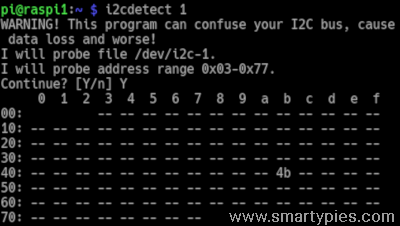
The existence and address of an I2C device can be checked by running i2cdetect 1 (1 for the internal bus number 1). It scans an address range 0x03-0x77 and in case your ADS1115 is connected properly and powered up, shows its address in a table. Address 0x48 is the default, but I'm using 0x4B, set by connecting ADDR with SCL.
Adafruit provides an extension board with this chip [3], to be run with their library [4]. This library requires several other libraries[5], but I chose to only use the Raspbian vanilla installation.
The regular Python GPIO library is Rpi.GPIO, often used through import RPi.GPIO as GPIO, documented here[6].
The System Management Bus (SMBus) protocol [7] , available in Python through import smbus is code compatible with the I2C protocol. Hardware spec limits DO vary [8] and must be observed when attaching SMB devices to I2C buses and vice versa. For our purposes here we are ok.
When I upgraded my Raspi 2B to the latest RaspiOS light version (without Desktop)[13], I had to install i2c-tools and python3-smbus manually with sudo apt install i2c-tools and sudo apt install python3-smbus.
Communication workflow
Generally the ADS1115 must be configured first for action. After some waiting time or alert, data can be read, one or more times. I2C commands for the ADS consist of 4 Bytes with the following meaning:
| device address (7Bit) | receive/transmit mode(1Bit) | pointer register (1Byte, 8Bit) register to be read or written | configuration/value word(2Byte, 16Bit) |
|---|---|---|---|
| 0x48-0x4B | 1 to write, 0 to read | 0x00 conversion register (values, RO) 0x01 configuration register (action, WO) 0x02 low threshold register (RW) 0x03 high threshold register (RW) | signed int, BigEndian, two complement format |
smbus methods
bus.write_word(address, register_pointer, configuration/threshold value) and
bus.read_word(address, register_pointer) take care of properly setting the read/write bit in the first Byte. The register pointer Byte is just one of the values listed above. Byte and Word values are read and written as Python integers.
The BigEndian-LittleEndian-Python integer conversion-confusion
As long as we push single Bytes, as for address and register, between Pi and ADS everything is fine. It gets tricky when dealing with 16Bit (=2 Byte = 1 Word) patterns, like configuration data or signed integers in the range from -2^15 to 2^15-1 for conversion and threshold values.
While the ADS1115 has BigEndian(=BE) Byte order, RaspberryPi-Hardware uses LittleEndian(=LE) Byte order.
For Words MSB (Most Significant Byte = Byte with the highest value) and LSB (Least Significant Byte = Byte with the lowest value) switch position, when transferred from one to the other, so a configuration value 0x8583 in BE sent by the Pi arrives as 0x8385 on the ADS.
To make up for this, simply swap Bytes before sending data to and after retrieving values from the ADS, e.g. value = (value>>8 | value<<8) &=0xFFFF. You will see this in the sample program as function swap2Bytes().
Even if the Raspberry uses LE on its hardware, Python uses BE in Bit-arrays for integers. Furthermore the integer type carries an extra sign field AND the array is not limited in length.
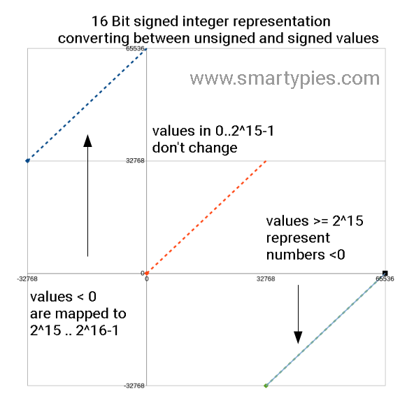
Consequently Python does not know about two complement representation of numbers, but these are represented as a bit pattern for the absolute value with the sign set accordingly [9]. For positive numbers in the range 0..(2^15-1) everything is fine after Byte swap.
In two complement for 2 Byte integers negative numbers are "mapped" to the range of 2^15..(2^16-1).
For numbers bigger or equal than 2^15 coming from the ADS, we subtract 2^16 to get the correct Python representation of the negative number. For negative numbers to be sent sent to the ADS, we can simply add 2^16. Not forgetting the necessary Byte swap, we arrive at functions like LEtoBE() and BEtoLE() in the sample program.
| function name in ads1115runner.py | code | comment |
|---|---|---|
| swap2Bytes |
def swap2Bytes(c): | exchange two Bytes |
| LEtoBE |
def LEtoBE(c): | convert from Raspberry LE to Python BE |
| BEtoLE |
def BEtoLE(c): | convert from Python BE to Raspberry LE |
Sample program
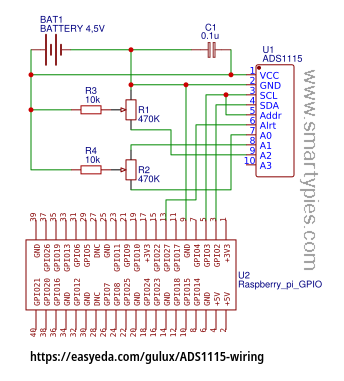
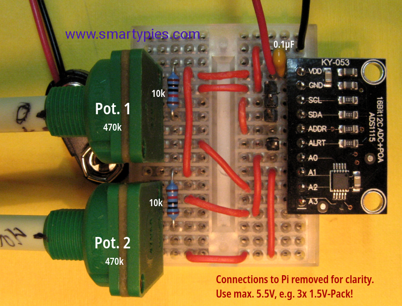
The sample program ADS1115Runner.py [10] and electric circuit [11] used here, demonstrate 4 different configurations, which will help you to grasp the concepts and go from there. After copy&paste into a file named "ADS1115Runner.py" and upload to Pi, run it with: python3 ADS1115Runner.py . Alternatively you can find it on Github [12].
| # | configuration | remarks |
|---|---|---|
| 1. | read a value from channel w/o notification | no values below 0, maximum value reached at middle position of potentiometer. |
| 2. | read a value with notification through GPIO | first alerted value is 0, because of alert pin level Active high. Avoided by setting configuration Bit 3 to 0 and wait for falling edge on GPIO. |
| 3. | compare 2 inputs | range from ca. -4000..4000 |
| 4. | value watchdog with thresholds | when the given window is left, alerts are triggered and values are reported. |
It is no full fledged ADS1115 configuration library. I simply use strings like 1-110-001-1-000-0-0-0-11 to define the different modes. These are converted into integers and Byte swapped, before being sent to the ADS. With a little practice you easily find the bits to set from the manual.
Currently the AdaFruit library does not support listening to conversion ready events, but just waits 'long enough' until a result is (should be) there.
Finally
- Never ever exceed the maximum allowable voltage of 5.5!
- You can stretch the value range in configuration 3 by setting the PGA Bits[11:9] accordingly.
- Make sure not to short-circuit GND with VDD, always put a resistor (e.g. 10k) before signal AIN lines. Latter can be connected to GND if a wrong multiplexer configuration is chosen.
- There are still many configuration options to explore.
- The integer conversion question can be rephrased for Python: Which positive number has the same Bit pattern as the the corresponding 2's complement signed integer? This can be answered for 16Bit integers from the graph above.
- Pasquale asked for sample code to do alternate readings of 2 connected probes (SoilWatch10 [14] from pino-tech). Here it is [15] and his final version [16]. His project MoGreen can be found in the Italian Raspberry forum [17].
- Have fun!
Links
- ADS1115 documentation (Texas Instruments): http://www.ti.com/lit/ds/symlink/ads1115.pdf
- I2C Bus Specification: https://i2c.info/i2c-bus-specification
- Adafruit extension board: https://www.adafruit.com/product/1085
- Adafruit CircuitPython library: https://github.com/adafruit/Adafruit_CircuitPython_ADS1x15 , deprecated since January 2019, Adafruit Python ADS1x15
- Adafruit GPIO library: https://github.com/adafruit/Adafruit_Python_GPIO
- Rpi.GPIO: https://sourceforge.net/p/raspberry-gpio-python/wiki/Home/
- SMBus Protocol: https://git.kernel.org/pub/scm/linux/kernel/git/torvalds/linux.git/plain/Documentation/i2c/smbus-protocol.rst
- Comparison of I2C vs. SMB protocol: https://pdfserv.maximintegrated.com/en/an/AN476.pdf
- This is the reason why you need to provide byte length and byte order in conversion functions to_bytes and from_bytes in Python. Other programming languages know about their integer type limits and convert directly. For example
"{:+x} {:+x}".format( 3, -3)in Python yields3 -3, while in Cprintf("%X %X", 3, -3)shows3 FFFFFFFD, the latter because regular C integers are 4 Bytes wide. - ADS1115Runner.py code
- test circuit on easyeada.com https://easyeda.com/gulux/ADS1115-wiring
- https://github.com/gulux/ADS1115Runner
- 2024-03-15-raspios-bookworm-armhf-lite
- pino-tech SoilWatch10, soil moisture sensor
- Sample program derived from ADS1115Runner.py for alternating readings of AIN0 and AIN1 against ground: ADSLooper.py
- Pasquale reads out the sensors once every couple of minutes, so no need for a loop. SoilWatch10-ADS1115-En.py
- MoGreen, monitoring greenhouse parameters (https://forum.raspberryitaly.com/showthread.php?tid=7373)